Carbon Fiber Filament Winder
2025
- Designed the tow head, carbon routing, and rotation system for a custom carbon fiber winder.
- Engineered sectioned, dovetail-jointed mandrels and a repeatable resin process for CFRP tubes.
- Built a disconnectable vacuum system and heat-shrink post-processing for better tube finish.
Collaborators
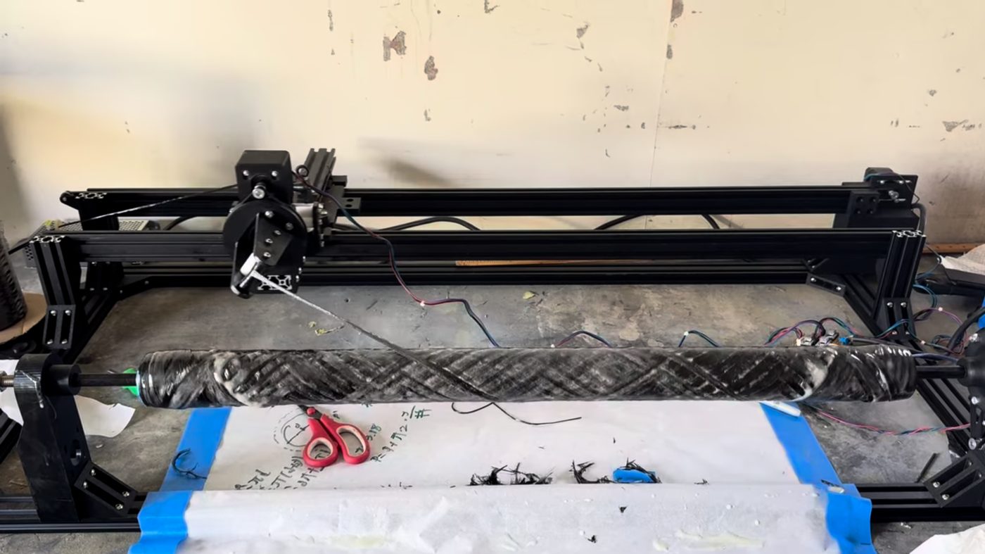
Overview
Built with Bike Builders of Berkeley, this project was a custom carbon fiber filament winder and post-processing system used to manufacture the CFRP (carbon fiber reinforced polymer) tubes for our downhill mountain bike frame. Carbon tow is wound under tension around removable mandrels, cured, and finished into structural tubes that bond to 3D-printed aluminum lugs. I focused on the winding hardware, the tooling, the resin process, and the post-processing that turns a raw wound tube into a clean, finished part.
Winding and tooling
I designed the tow head and the carbon routing system that guides and tensions the fiber as it feeds onto the mandrel, along with the hex shaft and rotation system that mounts to the motor and spins the mandrel throughout a wind.
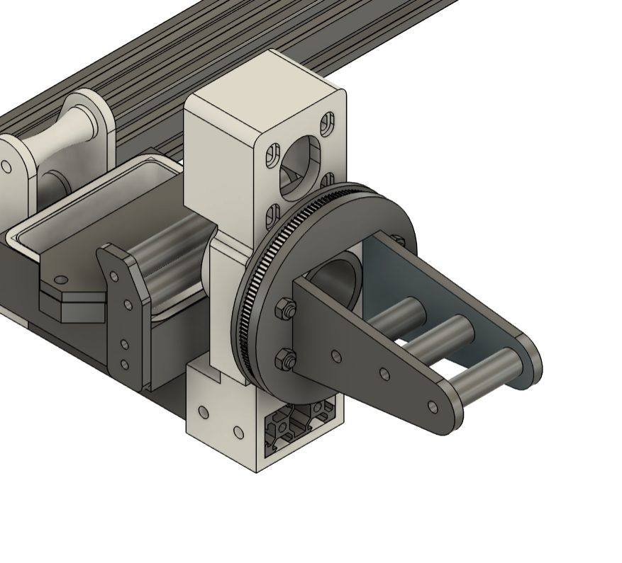 Tow head (CAD)
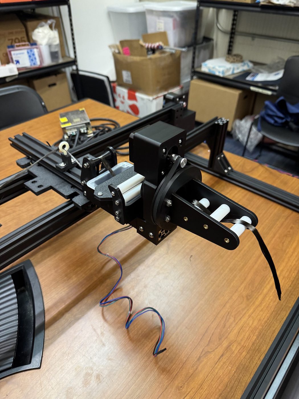 Tow head
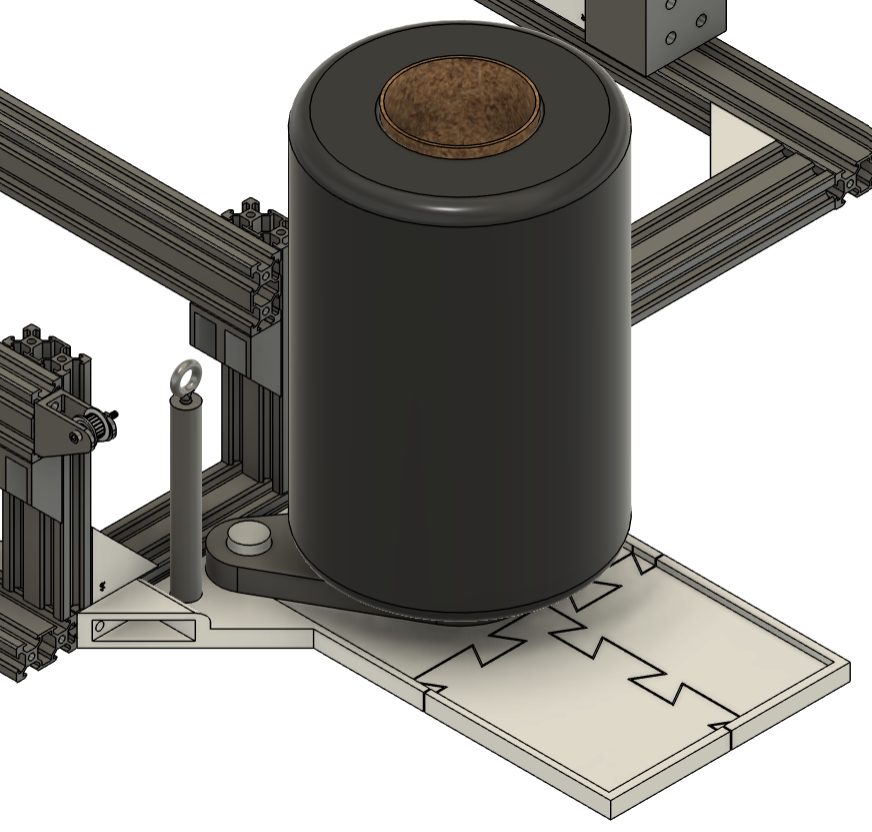 Tow holder (CAD)
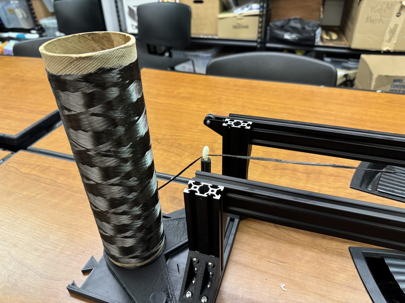 Tow holder
To keep the mandrels rigid while still 3D printable, I designed them in multiple sections joined by dovetail joints. This let us print each mandrel in pieces and assemble a stiff, accurate core that held its shape under winding tension.
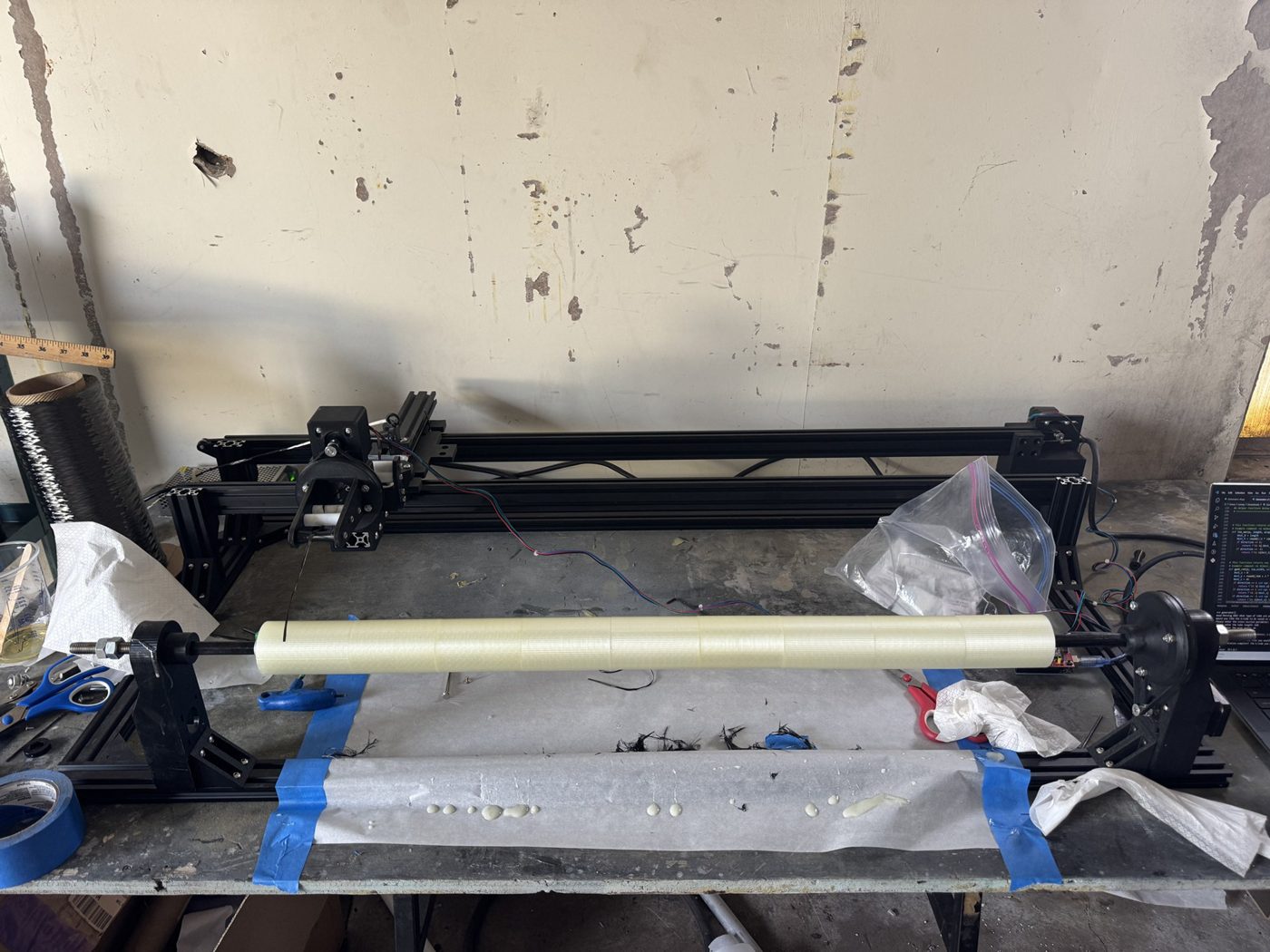 Sectioned mandrel with dovetail joints
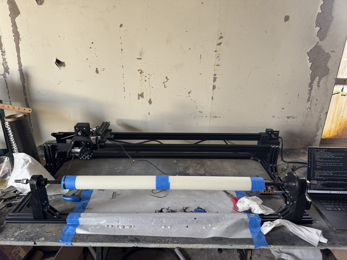 Sectioned mandrel with dovetail joints
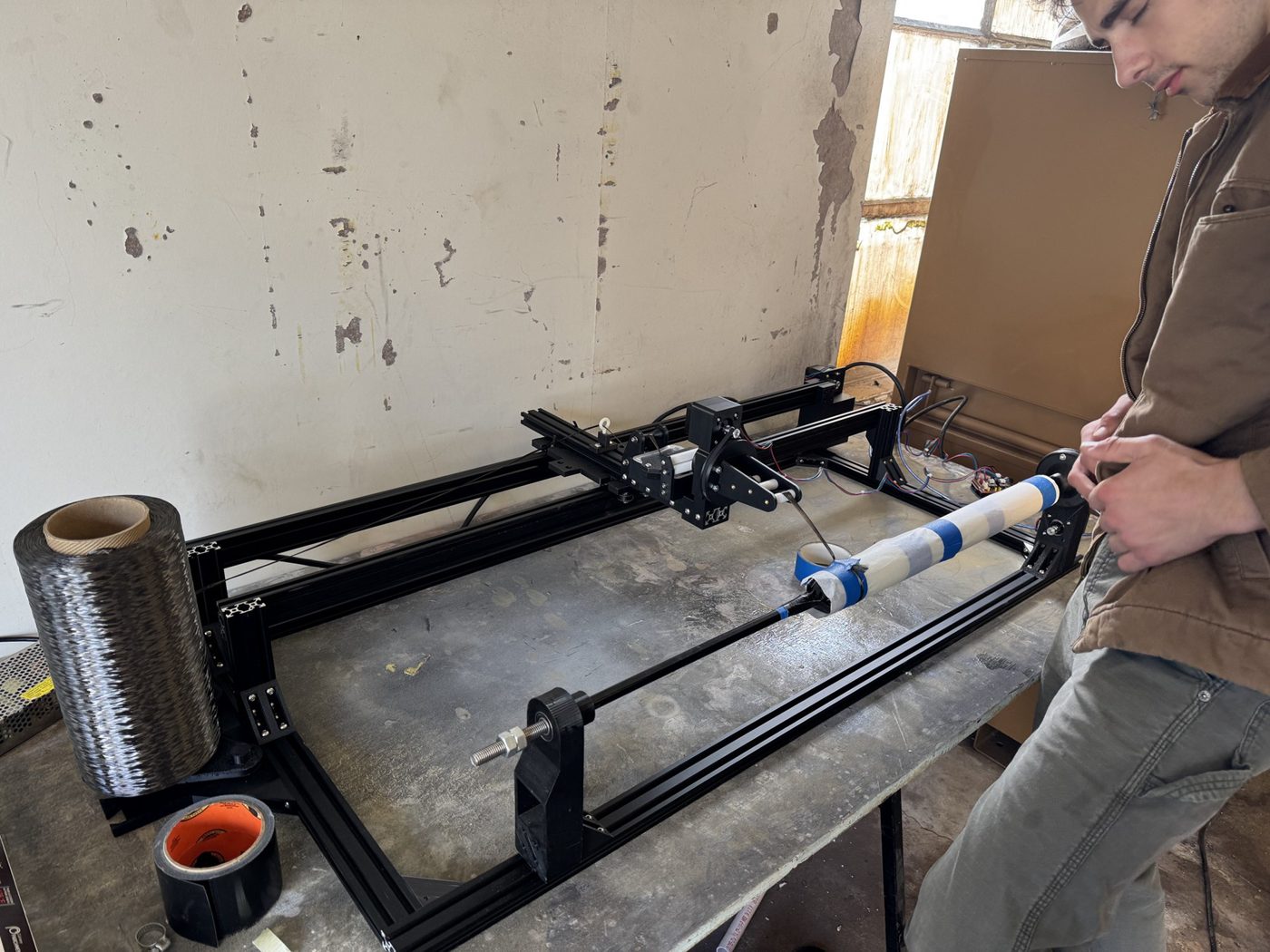 Sectioned mandrel with dovetail joints
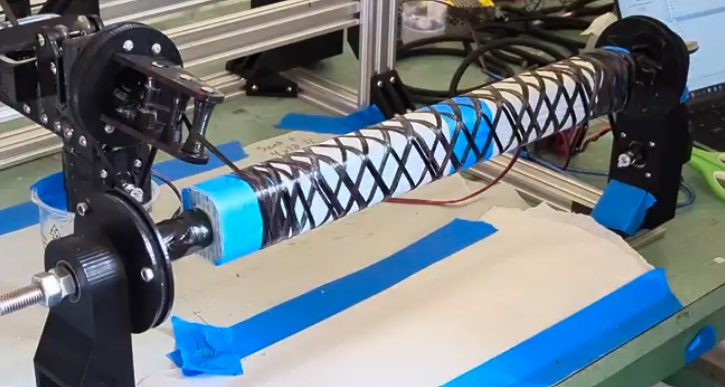 Filament winding
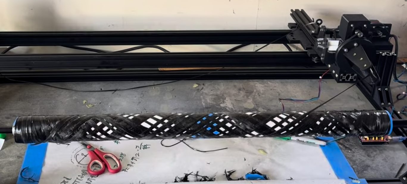 Filament winding
Resin control
To control the fiber-to-resin ratio in each tube, I developed a simple, repeatable method: weighing the tow spool before and after a wind to measure the fiber mass, then comparing it to the final cured tube weight to back out the resin content. This gave us a consistent way to target resin ratios across tubes.
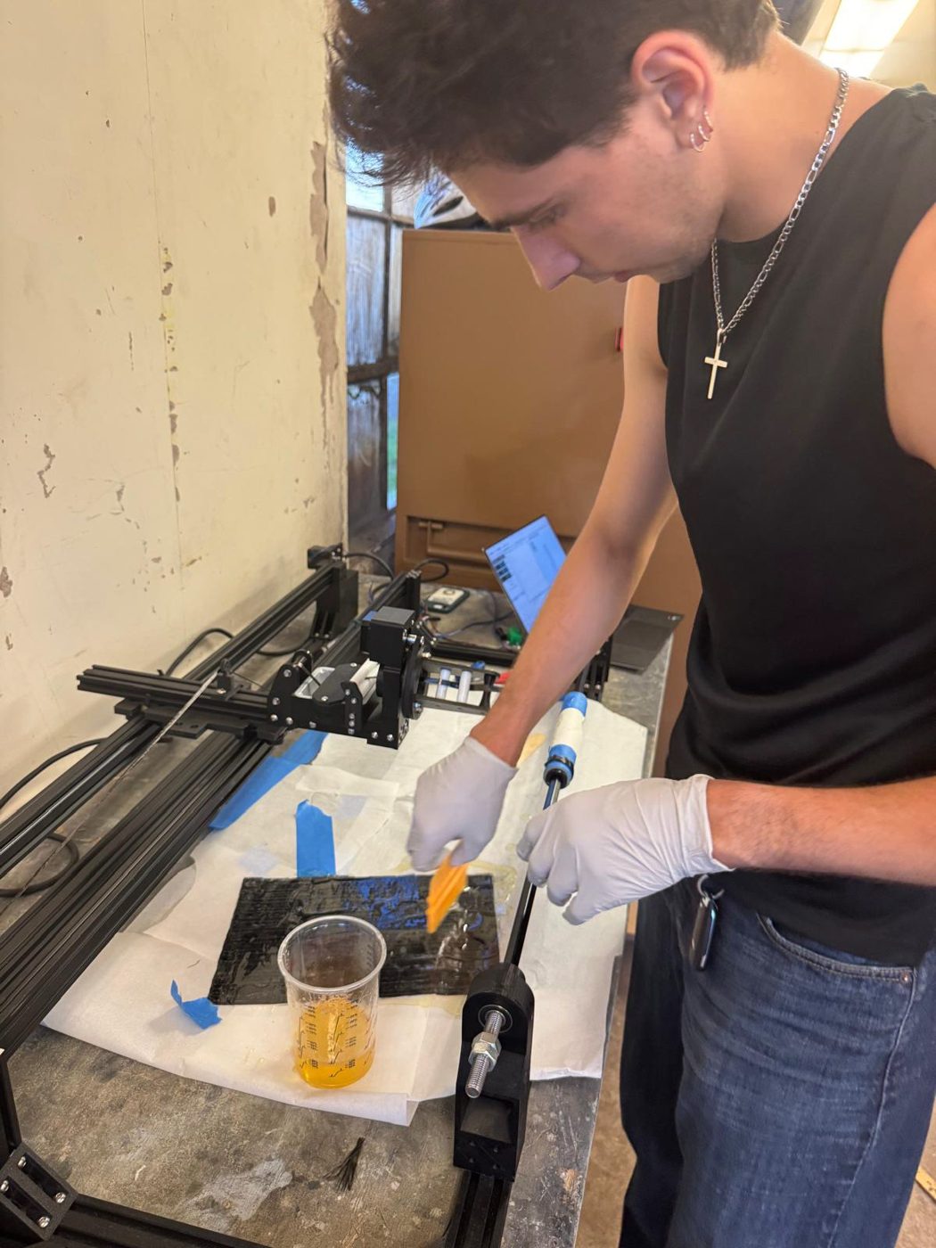 Adding unidirectional fiber
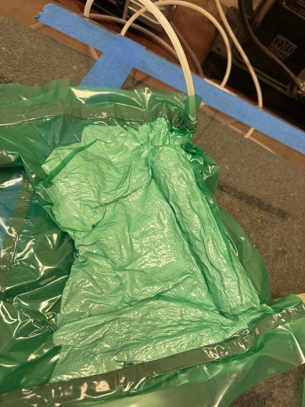 Wound tube in a vacuum bag
Post-processing
I designed the post-processing process end to end. I built a vacuum chamber and set up a new disconnectable vacuum system so bags could be sealed and left to cure off the pump, even at home, which freed up the pump between runs. I also designed a heat-shrink system that wraps the wound tube to apply extra pressure, squeeze out excess resin, and produce an optimal surface finish.
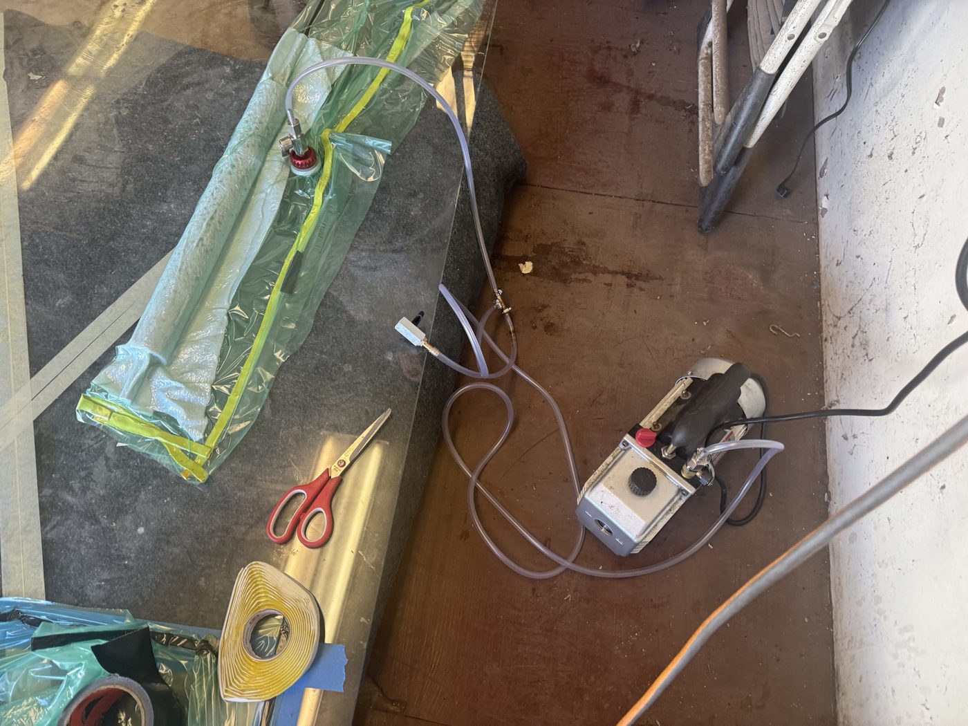 Vacuum chamber and disconnectable vacuum system
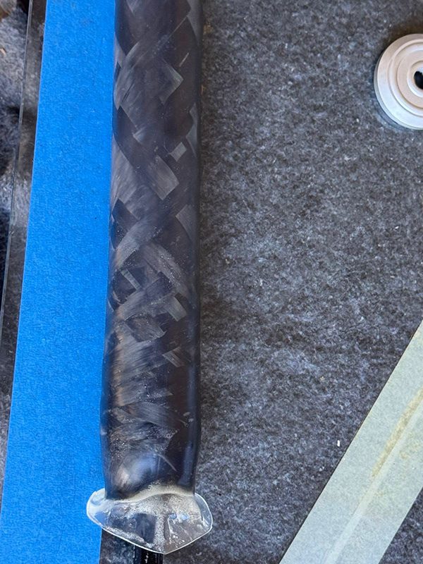 Heat-shrink surface finishing
Results
Together, these systems produced the finished CFRP tubes for the frame, which were bonded onto the aluminum lugs to complete the bike.
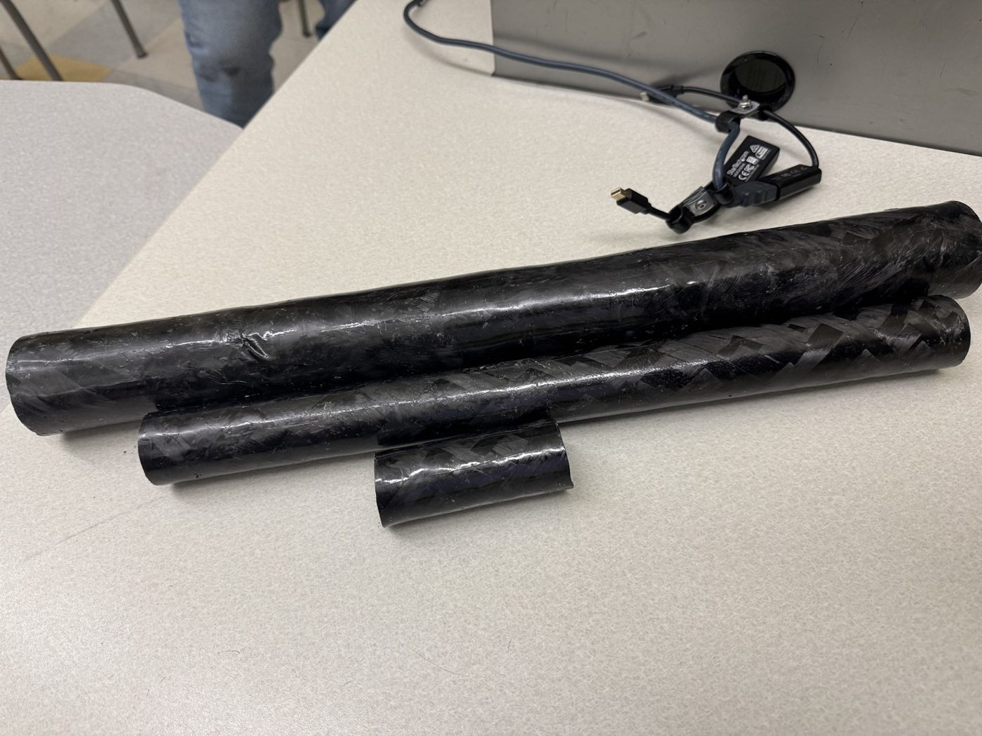 Finished tubes
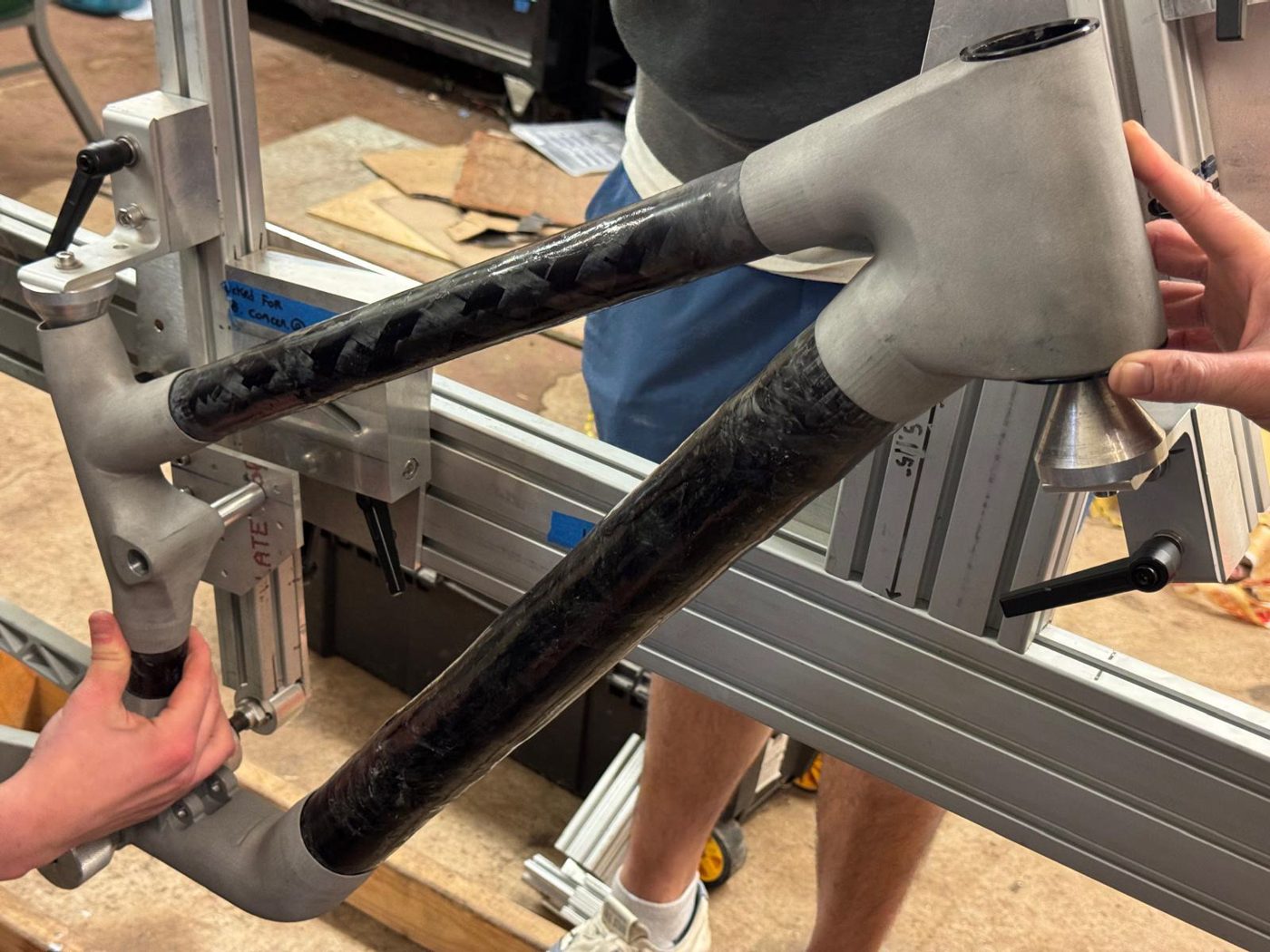 Tubes mounted on the frame
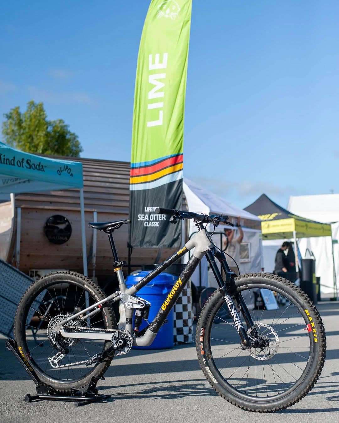 The finished bike
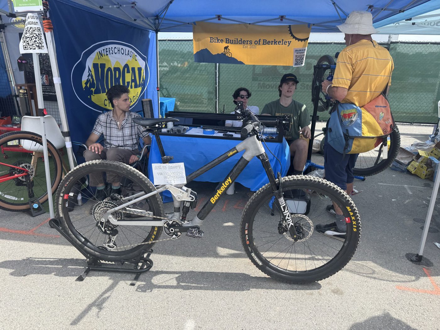 At the booth